Adding sensors on a robot#
While the asset classes allow us to create and simulate the physical embodiment of the robot, sensors help in obtaining information about the environment. They typically update at a lower frequency than the simulation and are useful for obtaining different proprioceptive and exteroceptive information. For example, a camera sensor can be used to obtain the visual information of the environment, and a contact sensor can be used to obtain the contact information of the robot with the environment.
In this tutorial, we will see how to add different sensors to a robot. We will use the ANYmal-C robot for this tutorial. The ANYmal-C robot is a quadrupedal robot with 12 degrees of freedom. It has 4 legs, each with 3 degrees of freedom. The robot has the following sensors:
A camera sensor on the head of the robot which provides RGB-D images
A height scanner sensor that provides terrain height information
Contact sensors on the feet of the robot that provide contact information
We continue this tutorial from the previous tutorial on Using the Interactive Scene,
where we learned about the scene.InteractiveScene class.
The Code#
The tutorial corresponds to the add_sensors_on_robot.py script in the
scripts/tutorials/04_sensors directory.
Code for add_sensors_on_robot.py
  1# Copyright (c) 2022-2026, The Isaac Lab Project Developers (https://github.com/isaac-sim/IsaacLab/blob/main/CONTRIBUTORS.md).
  2# All rights reserved.
  3#
  4# SPDX-License-Identifier: BSD-3-Clause
  5
  6"""
  7This script demonstrates how to add and simulate on-board sensors for a robot.
  8
  9We add the following sensors on the quadruped robot, ANYmal-C (ANYbotics):
 10
 11* USD-Camera: This is a camera sensor that is attached to the robot's base.
 12* Height Scanner: This is a height scanner sensor that is attached to the robot's base.
 13* Contact Sensor: This is a contact sensor that is attached to the robot's feet.
 14
 15.. code-block:: bash
 16
 17    # Usage
 18    ./isaaclab.sh -p scripts/tutorials/04_sensors/add_sensors_on_robot.py --enable_cameras --viz kit
 19
 20"""
 21
 22"""Launch Isaac Sim Simulator first."""
 23
 24import argparse
 25
 26from isaaclab.app import AppLauncher
 27
 28# add argparse arguments
 29parser = argparse.ArgumentParser(description="Tutorial on adding sensors on a robot.")
 30parser.add_argument("--num_envs", type=int, default=2, help="Number of environments to spawn.")
 31# append AppLauncher cli args
 32AppLauncher.add_app_launcher_args(parser)
 33# parse the arguments
 34args_cli = parser.parse_args()
 35
 36# launch omniverse app
 37app_launcher = AppLauncher(args_cli)
 38simulation_app = app_launcher.app
 39
 40"""Rest everything follows."""
 41
 42import torch
 43
 44import isaaclab.sim as sim_utils
 45from isaaclab.assets import ArticulationCfg, AssetBaseCfg
 46from isaaclab.scene import InteractiveScene, InteractiveSceneCfg
 47from isaaclab.sensors import CameraCfg, ContactSensorCfg, RayCasterCfg, patterns
 48from isaaclab.utils.configclass import configclass
 49
 50##
 51# Pre-defined configs
 52##
 53from isaaclab_assets.robots.anymal import ANYMAL_C_CFG  # isort: skip
 54
 55
 56@configclass
 57class SensorsSceneCfg(InteractiveSceneCfg):
 58    """Design the scene with sensors on the robot."""
 59
 60    # ground plane
 61    ground = AssetBaseCfg(prim_path="/World/defaultGroundPlane", spawn=sim_utils.GroundPlaneCfg())
 62
 63    # lights
 64    dome_light = AssetBaseCfg(
 65        prim_path="/World/Light", spawn=sim_utils.DomeLightCfg(intensity=3000.0, color=(0.75, 0.75, 0.75))
 66    )
 67
 68    # robot
 69    robot: ArticulationCfg = ANYMAL_C_CFG.replace(prim_path="{ENV_REGEX_NS}/Robot")
 70
 71    # sensors
 72    camera = CameraCfg(
 73        prim_path="{ENV_REGEX_NS}/Robot/base/front_cam",
 74        update_period=0.1,
 75        height=480,
 76        width=640,
 77        data_types=["rgb", "distance_to_image_plane"],
 78        spawn=sim_utils.PinholeCameraCfg(
 79            focal_length=24.0, focus_distance=400.0, horizontal_aperture=20.955, clipping_range=(0.1, 1.0e5)
 80        ),
 81        offset=CameraCfg.OffsetCfg(pos=(0.510, 0.0, 0.015), rot=(0.5, -0.5, 0.5, -0.5), convention="ros"),
 82    )
 83    height_scanner = RayCasterCfg(
 84        prim_path="{ENV_REGEX_NS}/Robot/base",
 85        update_period=0.02,
 86        offset=RayCasterCfg.OffsetCfg(pos=(0.0, 0.0, 20.0)),
 87        ray_alignment="yaw",
 88        pattern_cfg=patterns.GridPatternCfg(resolution=0.1, size=[1.6, 1.0]),
 89        debug_vis=True,
 90        mesh_prim_paths=["/World/defaultGroundPlane"],
 91    )
 92    contact_forces = ContactSensorCfg(
 93        prim_path="{ENV_REGEX_NS}/Robot/.*_FOOT", update_period=0.0, history_length=6, debug_vis=True
 94    )
 95
 96
 97def run_simulator(sim: sim_utils.SimulationContext, scene: InteractiveScene):
 98    """Run the simulator."""
 99    # Define simulation stepping
100    sim_dt = sim.get_physics_dt()
101    sim_time = 0.0
102    count = 0
103
104    # Simulate physics
105    while simulation_app.is_running():
106        # Reset
107        if count % 500 == 0:
108            # reset counter
109            count = 0
110            # reset the scene entities
111            # root state
112            # we offset the root state by the origin since the states are written in simulation world frame
113            # if this is not done, then the robots will be spawned at the (0, 0, 0) of the simulation world
114            root_pose = scene["robot"].data.default_root_pose.torch.clone()
115            root_pose[:, :3] += scene.env_origins
116            scene["robot"].write_root_pose_to_sim_index(root_pose=root_pose)
117            root_vel = scene["robot"].data.default_root_vel.torch.clone()
118            scene["robot"].write_root_velocity_to_sim_index(root_velocity=root_vel)
119            # set joint positions with some noise
120            joint_pos, joint_vel = (
121                scene["robot"].data.default_joint_pos.torch.clone(),
122                scene["robot"].data.default_joint_vel.torch.clone(),
123            )
124            joint_pos += torch.rand_like(joint_pos) * 0.1
125            scene["robot"].write_joint_position_to_sim_index(position=joint_pos)
126            scene["robot"].write_joint_velocity_to_sim_index(velocity=joint_vel)
127            # clear internal buffers
128            scene.reset()
129            print("[INFO]: Resetting robot state...")
130        # Apply default actions to the robot
131        # -- generate actions/commands
132        targets = scene["robot"].data.default_joint_pos.torch
133        # -- apply action to the robot
134        scene["robot"].set_joint_position_target_index(target=targets)
135        # -- write data to sim
136        scene.write_data_to_sim()
137        # perform step
138        sim.step()
139        # update sim-time
140        sim_time += sim_dt
141        count += 1
142        # update buffers
143        scene.update(sim_dt)
144
145        # print information from the sensors
146        print("-------------------------------")
147        print(scene["camera"])
148        print("Received shape of rgb   image: ", scene["camera"].data.output["rgb"].shape)
149        print("Received shape of depth image: ", scene["camera"].data.output["distance_to_image_plane"].shape)
150        print("-------------------------------")
151        print(scene["height_scanner"])
152        print(
153            "Received max height value: ",
154            torch.max(scene["height_scanner"].data.ray_hits_w.torch[..., -1]).item(),
155        )
156        print("-------------------------------")
157        print(scene["contact_forces"])
158        print("Received max contact force of: ", torch.max(scene["contact_forces"].data.net_forces_w).item())
159
160
161def main():
162    """Main function."""
163
164    # Initialize the simulation context
165    sim_cfg = sim_utils.SimulationCfg(dt=0.005, device=args_cli.device)
166    sim = sim_utils.SimulationContext(sim_cfg)
167    # Set main camera
168    sim.set_camera_view(eye=[3.5, 3.5, 3.5], target=[0.0, 0.0, 0.0])
169    # Design scene
170    scene_cfg = SensorsSceneCfg(num_envs=args_cli.num_envs, env_spacing=2.0)
171    scene = InteractiveScene(scene_cfg)
172    # Play the simulator
173    sim.reset()
174    # Now we are ready!
175    print("[INFO]: Setup complete...")
176    # Run the simulator
177    run_simulator(sim, scene)
178
179
180if __name__ == "__main__":
181    # run the main function
182    main()
183    # close sim app
184    simulation_app.close()
The Code Explained#
Similar to the previous tutorials, where we added assets to the scene, the sensors are also added
to the scene using the scene configuration. All sensors inherit from the sensors.SensorBase class
and are configured through their respective config classes. Each sensor instance can define its own
update period, which is the frequency at which the sensor is updated. The update period is specified
in seconds through the sensors.SensorBaseCfg.update_period attribute.
Depending on the specified path and the sensor type, the sensors are attached to the prims in the scene. They may have an associated prim that is created in the scene or they may be attached to an existing prim. For instance, the camera sensor has a corresponding prim that is created in the scene, whereas for the contact sensor, activating the contact reporting is a property on a rigid body prim.
In the following, we introduce the different sensors we use in this tutorial and how they are configured.
For more description about them, please check the sensors module.
Camera sensor#
A camera is defined using the sensors.CameraCfg. It is based on the USD Camera sensor and
the different data types are captured using Omniverse Replicator API. Since it has a corresponding prim
in the scene, the prims are created in the scene at the specified prim path.
The configuration of the camera sensor includes the following parameters:
spawn: The type of USD camera to create. This can be eitherPinholeCameraCfgorFisheyeCameraCfg.offset: The offset of the camera sensor from the parent prim.data_types: The data types to capture. This can bergb,distance_to_image_plane,normals, or other types supported by the USD Camera sensor.
To attach an RGB-D camera sensor to the head of the robot, we specify an offset relative to the base
frame of the robot. The offset is specified as a translation and rotation relative to the base frame,
and the convention in which the offset is specified.
In the following, we show the configuration of the camera sensor used in this tutorial. We set the
update period to 0.1s, which means that the camera sensor is updated at 10Hz. The prim path expression is
set to {ENV_REGEX_NS}/Robot/base/front_cam where the {ENV_REGEX_NS} is the environment namespace,
"Robot" is the name of the robot, "base" is the name of the prim to which the camera is attached,
and "front_cam" is the name of the prim associated with the camera sensor.
    camera = CameraCfg(
        prim_path="{ENV_REGEX_NS}/Robot/base/front_cam",
        update_period=0.1,
        height=480,
        width=640,
        data_types=["rgb", "distance_to_image_plane"],
        spawn=sim_utils.PinholeCameraCfg(
            focal_length=24.0, focus_distance=400.0, horizontal_aperture=20.955, clipping_range=(0.1, 1.0e5)
        ),
        offset=CameraCfg.OffsetCfg(pos=(0.510, 0.0, 0.015), rot=(0.5, -0.5, 0.5, -0.5), convention="ros"),
    )
Height scanner#
The height-scanner is implemented as a virtual sensor using the NVIDIA Warp ray-casting kernels.
Through the sensors.RayCasterCfg, we can specify the pattern of rays to cast and the
meshes against which to cast the rays. By default, spawn creates
a plain USD Xform at prim_path to serve as the sensor’s
attachment frame, similar to how sensors.CameraCfg spawns a Camera prim.
For this tutorial, the ray-cast based height scanner is attached under the base frame of the robot.
The pattern of rays is specified using the pattern attribute. For
a uniform grid pattern, we specify the pattern using GridPatternCfg.
Since we only care about the height information, we do not need to consider the roll and pitch
of the robot. Hence, we set the ray_alignment to “yaw”.
For the height-scanner, you can visualize the points where the rays hit the mesh. This is done
by setting the debug_vis attribute to true.
The entire configuration of the height-scanner is as follows:
    height_scanner = RayCasterCfg(
        prim_path="{ENV_REGEX_NS}/Robot/base",
        update_period=0.02,
        offset=RayCasterCfg.OffsetCfg(pos=(0.0, 0.0, 20.0)),
        ray_alignment="yaw",
        pattern_cfg=patterns.GridPatternCfg(resolution=0.1, size=[1.6, 1.0]),
        debug_vis=True,
        mesh_prim_paths=["/World/defaultGroundPlane"],
    )
Contact sensor#
Contact sensors wrap around the PhysX contact reporting API to obtain the contact information of the robot
with the environment. Since it relies of PhysX, the contact sensor expects the contact reporting API
to be enabled on the rigid bodies of the robot. This can be done by setting the
activate_contact_sensors to true in the asset configuration.
Through the sensors.ContactSensorCfg, it is possible to specify the prims for which we want to
obtain the contact information. Additional flags can be set to obtain more information about
the contact, such as the contact air time, contact forces between filtered prims, etc.
In this tutorial, we attach the contact sensor to the feet of the robot. The feet of the robot are
named "LF_FOOT", "RF_FOOT", "LH_FOOT", and "RH_FOOT". We pass a Regex expression
".*_FOOT" to simplify the prim path specification. This Regex expression matches all prims that
end with "_FOOT".
We set the update period to 0 to update the sensor at the same frequency as the simulation. Additionally, for contact sensors, we can specify the history length of the contact information to store. For this tutorial, we set the history length to 6, which means that the contact information for the last 6 simulation steps is stored.
The entire configuration of the contact sensor is as follows:
    contact_forces = ContactSensorCfg(
        prim_path="{ENV_REGEX_NS}/Robot/.*_FOOT", update_period=0.0, history_length=6, debug_vis=True
    )
Running the simulation loop#
Similar to when using assets, the buffers and physics handles for the sensors are initialized only
when the simulation is played, i.e., it is important to call sim.reset() after creating the scene.
    # Play the simulator
    sim.reset()
Besides that, the simulation loop is similar to the previous tutorials. The sensors are updated as part of the scene update and they internally handle the updating of their buffers based on their update periods.
The data from the sensors can be accessed through their data attribute. As an example, we show how
to access the data for the different sensors created in this tutorial:
        # print information from the sensors
        print("-------------------------------")
        print(scene["camera"])
        print("Received shape of rgb   image: ", scene["camera"].data.output["rgb"].shape)
        print("Received shape of depth image: ", scene["camera"].data.output["distance_to_image_plane"].shape)
        print("-------------------------------")
        print(scene["height_scanner"])
        print(
            "Received max height value: ",
            torch.max(scene["height_scanner"].data.ray_hits_w.torch[..., -1]).item(),
        )
        print("-------------------------------")
        print(scene["contact_forces"])
        print("Received max contact force of: ", torch.max(scene["contact_forces"].data.net_forces_w).item())
The Code Execution#
Now that we have gone through the code, let’s run the script and see the result:
./isaaclab.sh -p scripts/tutorials/04_sensors/add_sensors_on_robot.py --num_envs 2 --enable_cameras --viz kit
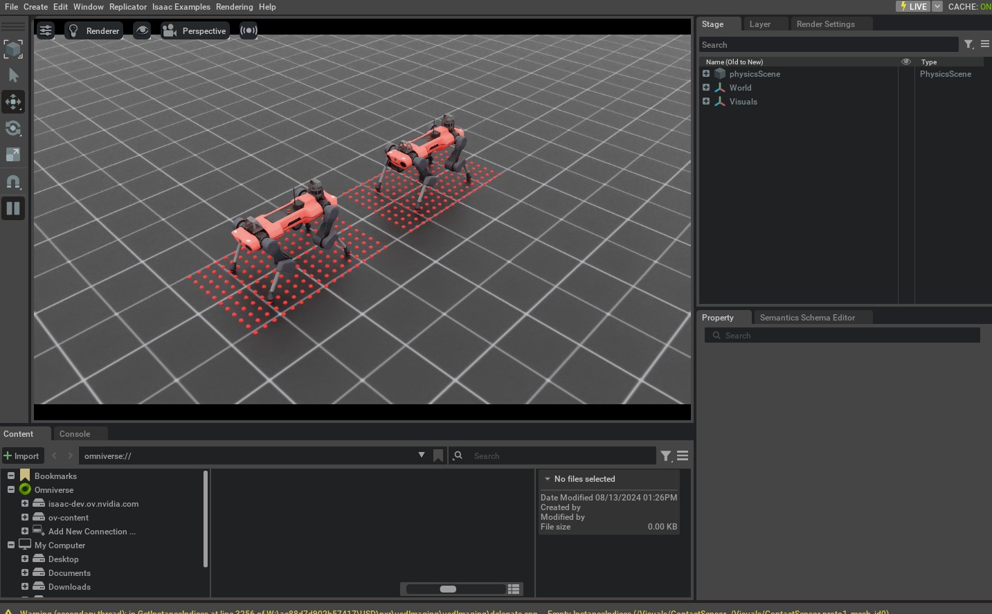
This command should open a stage with a ground plane, lights, and two quadrupedal robots. Around the robots, you should see red spheres that indicate the points where the rays hit the mesh. Additionally, you can switch the viewport to the camera view to see the RGB image captured by the camera sensor. Please check here for more information on how to switch the viewport to the camera view.
To stop the simulation, you can either close the window, or press Ctrl+C in the terminal.
While in this tutorial, we went over creating and using different sensors, there are many more sensors
available in the sensors module. We include minimal examples of using these sensors in the
scripts/tutorials/04_sensors directory. For completeness, these scripts can be run using the
following commands:
# Frame Transformer
./isaaclab.sh -p scripts/tutorials/04_sensors/run_frame_transformer.py --viz kit

# Ray Caster
./isaaclab.sh -p scripts/tutorials/04_sensors/run_ray_caster.py --viz kit

# Ray Caster Camera
./isaaclab.sh -p scripts/tutorials/04_sensors/run_ray_caster_camera.py --viz kit

# USD Camera
./isaaclab.sh -p scripts/tutorials/04_sensors/run_usd_camera.py --enable_cameras --viz kit