Comparing Simulations Between Isaac Gym and Isaac Lab#
When migrating simulations from Isaac Gym to Isaac Lab, it is sometimes helpful to compare the simulation configurations in Isaac Gym and Isaac Lab to identify differences between the two setups. There may be differences in how default values are interpreted, how the importer treats certain hierarchies of bodies, and how values are scaled. The only way to be certain that two simulations are equivalent in the eyes of PhysX is to record a simulation trace of both setups and compare them by inspecting them side-by-side. This approach works because PhysX is the same underlying engine for both Isaac Gym and Isaac Lab, albeit with different versions.
Recording to PXD2 in Isaac Gym Preview Release#
Simulation traces in Isaac Gym can be recorded using the built-in PhysX Visual Debugger (PVD)
file output feature. Set the operating system environment variable GYM_PVD_FILE to the
desired output file path; the .pxd2 file extension will be appended automatically.
For detailed instructions, refer to the tuning documentation included with Isaac Gym:
isaacgym/docs/_sources/programming/tuning.rst.txt
Note
This file reference is provided because Isaac Gym does not have its documentation available online.
Recording to OVD in Isaac Lab#
To record an OVD simulation trace file in Isaac Lab, you must set the appropriate Isaac Sim Kit
arguments. It is important that the omniPvdOvdRecordingDirectory variable is set before
omniPvdOutputEnabled is set to true.
./isaaclab.sh -p scripts/benchmarks/benchmark_non_rl.py --task <task_name> \
    --kit_args="--/persistent/physics/omniPvdOvdRecordingDirectory=/tmp/myovds/ \
    --/physics/omniPvdOutputEnabled=true"
This example outputs a series of OVD files to the /tmp/myovds/ directory.
If the --kit_args argument does not work in your particular setup, you can set the Kit arguments
manually by editing the following file directly within the Isaac Sim source code:
source/extensions/isaacsim.simulation_app/isaacsim/simulation_app/simulation_app.py
Append the following lines after the args = [] block:
args.append("--/persistent/physics/omniPvdOvdRecordingDirectory=/path/to/output/ovds/")
args.append("--/physics/omniPvdOutputEnabled=true")
Inspecting PXD2 and OVD Files#
By opening the PXD2 file in a PVD viewer and the OVD file in OmniPVD (a Kit extension), you can manually compare the two simulation runs and their respective parameters.
PhysX Visual Debugger (PVD) for PXD2 Files
Download the PVD viewer from the NVIDIA Developer Tools page:
Both version 2 and version 3 of the PVD viewer are compatible with PXD2 files.
OmniPVD for OVD Files
To view OVD files, enable the OmniPVD extension in the Isaac Sim application. For detailed instructions, refer to the OmniPVD developer guide:
Inspecting Contact Gizmos in OmniPVD
To inspect contact points between objects, enable the contact gizmos in OmniPVD. Ensure that the simulation frame is set to PRE (pre-simulation frames of each simulation step) in the OmniPVD timeline, or set the replay mode to PRE. This allows you to visualize contact information before the solver processes each step.
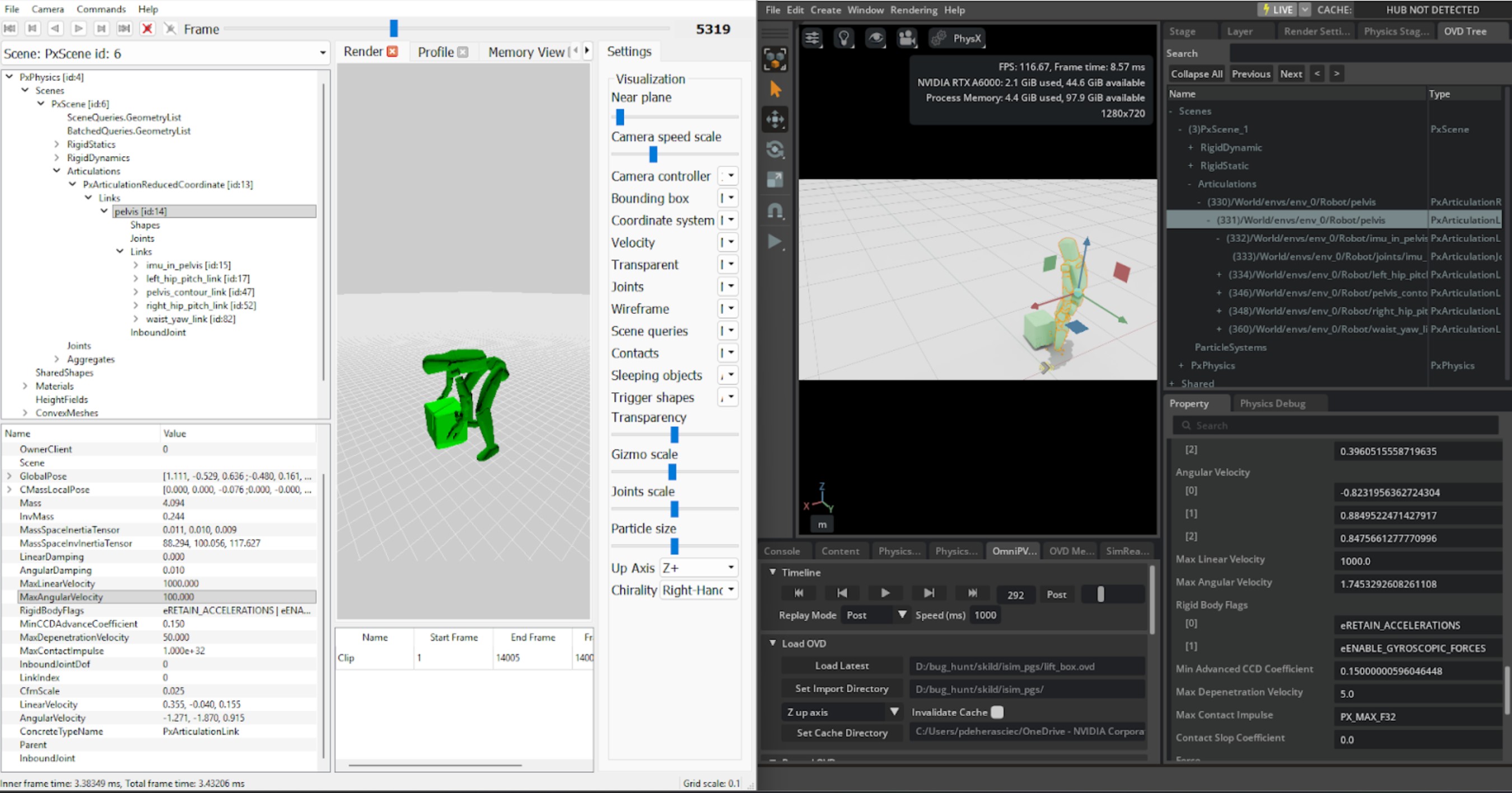
Comparing PVD and OVD Files
Using the PVD viewer and the OmniPVD extension, you can now compare the simulations side-by-side to identify configuration differences. On the left is PVD for PXD2 inspection and on the right is the OmniPVD extension loaded to inspect OVD files.
Parameters to Verify During Simulation Comparison#
For PhysX articulations, each attribute is useful to inspect because it reveals how the link or shape will actually behave in contact, under drives, and at constraints. Below, each attribute is expanded with why it matters for debugging and tuning simulations.
PxArticulationLink#
Each link behaves like a rigid body with mass properties, damping, velocity limits, and contact-resolution limits. Inspecting these helps explain stability issues, jitter, and odd responses to forces.
Mass Properties#
- Mass
Determines how strongly the link accelerates under forces and how it shares impulses in collisions and joint constraints.
When to inspect: Understand why a link seems “too heavy” (barely moves when pushed) or “too light” (flies around from small impulses), and to detect inconsistent mass distribution across a chain that can cause unrealistic motion or joint stress.
- Center of Mass (pose)
Controls where forces effectively act and how the link balances.
When to inspect: A character or mechanism tips over unexpectedly or feels unbalanced; an offset COM can cause unrealistic torque for the same contact.
- Inertia Tensor / Inertia Scale
Defines rotational resistance about each axis.
When to inspect: Links are too easy or too hard to spin relative to their mass, which affects joint drive tuning and impact responses.
Damping Properties#
- Linear Damping
Models velocity-proportional drag on translation; higher values make links lose linear speed faster.
When to inspect: Links slide too far (damping too low) or feel “underwater” (damping too high), or when articulation energy seems to vanish without obvious contact.
- Angular Damping
Models drag on rotation; higher values make spinning links slow more quickly.
When to inspect: Links keep spinning after impacts or motor drives (too low), or joints feel “sticky” and fail to swing freely under gravity (too high).
Velocity Properties#
- Linear Velocity
Instantaneous world-space translational velocity of the link.
When to inspect: Verify whether joint motors, gravity, or contacts are generating expected motion, detect numerical explosions (huge spikes), and correlate with CCD thresholds and max linear velocity clamping.
- Angular Velocity
Instantaneous world-space rotational velocity.
When to inspect: Verify joint drives, impacts, or constraints are producing the correct rotation; spot runaway spin that can cause instability or tunneling before clamping takes effect.
- Max Linear Velocity
Upper bound PhysX uses to clamp linear speed before solving, intended to prevent numerical issues from extremely fast motion.
When to inspect: Objects start tunneling or simulations explode at high speeds. If too high, links can move too far in one step; too low, they may appear unnaturally capped like “speed-limited” robots.
- Max Angular Velocity
Upper bound for angular speed; PhysX clamps angular velocity similarly to linear velocity.
When to inspect: Links spin unrealistically fast after collisions or drives (value too large), or rotation looks unnaturally limited, especially for wheels or rotors that should rotate quickly (value too small).
Contact Resolution Properties#
- Max Depenetration Velocity
Limits how much corrective velocity the solver may add in one step to resolve penetrations at contacts.
When to inspect: Overlapping links “explode” outward or jitter after starting interpenetrating (too high), or embedded links separate too slowly and appear stuck together (too low).
- Max Contact Impulse
Caps the impulse the solver can apply at contacts; per-body limit, with the actual contact limit being the minimum of the two bodies’ values.
When to inspect: Contacts feel too soft (bodies interpenetrate deeply or sink into the environment) or too rigid (sharp impulses causing ringing or bouncing), or when tuning “soft collisions” like rubber or skin-like surfaces.
State and Behavior Flags#
- Kinematic vs Dynamic flag / Disable gravity
Indicates whether a link is driven kinematically or fully simulated, and whether gravity affects it.
When to inspect: Parts appear frozen, snap directly to poses, or ignore gravity, which can drastically change articulation behavior.
- Sleep thresholds (linear, angular) and wake counter
Control when a link is allowed to go to sleep and stop simulating.
When to inspect: Articulations sleep too early (stopping motion) or never sleep (wasting performance and causing low-amplitude jitter).
PxArticulationJoint#
The inbound joint defines relative motion between a link and its parent. Inspecting motion and related parameters explains limits, constraints, and how drives shape articulation pose and stability.
Joint Configuration#
- Motion
Per-axis setting (locked, limited, free) that defines which degrees of freedom the joint allows and whether ranges are restricted.
When to inspect: A link moves in an unexpected direction (axis wrongly set to free), hits a hard stop sooner or later than expected (limit vs locked), or seems unconstrained because an axis is mistakenly left free.
- Joint Type / Axes definition
Choice of revolute, prismatic, spherical, etc., and the local joint frames that define axes.
When to inspect: A “hinge” behaves more like a ball joint or slides unexpectedly; incorrect type or frame alignment easily produces weird motions.
- Limits (swing, twist, linear)
Specify allowed angular or linear ranges and often include stiffness/damping.
When to inspect: Joints hyper-extend, clip through geometry, or suddenly snap at boundaries; mis-set limits cause popping and instability.
Drive Properties#
- Drive target position (orientation) and target velocity
Desired relative pose and relative velocity that drives the articulation, often using spring-damper models.
When to inspect: Controllers are too slow or overshoot and oscillate—target values and drive parameters must match link mass and inertia.
- Drive stiffness and damping (spring strength, tangential damping)
Control how aggressively the joint tries to reach the target pose and how much overshoot is damped.
When to inspect: Joints buzz or oscillate under load (stiffness high, damping low) or feel unresponsive and “rubbery” (stiffness low).
- Joint friction / resistance (if configured)
Adds resistance even without explicit damping in drives.
When to inspect: Passive joints keep swinging too long, or appear stuck even without drives.
PxShape#
Shapes attached to links determine collision representation and contact behavior. Even if they are internal in OmniPhysics, their properties have a strong impact on stability, contact timing, and visual alignment.
Collision Offsets#
- Rest Offset
Distance at which two shapes come to rest; sum of their rest offsets defines the separation where they “settle”.
When to inspect: Graphics and collision appear misaligned (gaps or visible intersections), or sliding over meshes is rough. Small positive offsets can smooth sliding, while zero offset tends to align exactly but may catch on geometry.
- Contact Offset
Distance at which contact generation begins; shapes whose distance is less than the sum of contact offsets generate contacts.
When to inspect: Contacts appear “too early” (objects seem to collide before visually touching, increasing contact count) or “too late” (tunneling or jitter). The difference between contact and rest offsets is crucial for predictive, stable contacts.
Geometry and Materials#
- Geometry type and dimensions
Box, sphere, capsule, convex, mesh, and the associated size parameters.
When to inspect: Collision footprint does not match the visual mesh—overly large shapes cause premature contacts; small shapes allow visual intersection and change leverage at contacts.
- Material(s): friction, restitution, compliance
Friction coefficients and restitution define sliding and bounciness.
When to inspect: An articulation foot skids too easily, sticks to the ground, or bounces unexpectedly. Wrong materials can make mechanisms unstable or unresponsive.
Shape Flags#
- Flag for simulation / query / trigger
Whether the shape participates in simulation contacts, raycasts only, or trigger events.
When to inspect: Contacts do not appear (shape set as query only) or triggers unexpectedly create physical collisions.
- Contact density (CCD flags, if used)
Continuous collision detection flags affecting how fast-moving links are handled.
When to inspect: Fast articulation parts tunnel through thin obstacles, or CCD is too aggressive and reduces performance.
PxRigidDynamic#
PxRigidDynamic is the core simulated rigid body type in PhysX, so inspecting its attributes is crucial
for understanding individual object behavior, stability, and performance in the scene. Many attributes
mirror PxArticulationLink, but a rigid dynamic is not constrained by articulation joints and can also
be used in kinematic mode.
Damping and Velocity Limits#
- Linear Damping
Adds velocity-proportional drag on translation.
When to inspect: Bodies slide too far or for too long (damping too low) or appear as if moving through thick fluid (damping too high), and when scenes lose energy faster than friction alone would suggest.
- Angular Damping
Adds drag on rotation, reducing angular velocity over time.
When to inspect: Spinning objects never settle or spin unrealistically long (too low), or they stop rotating almost immediately after impact or motor impulses (too high).
- Linear Velocity
Current translational velocity used by the integrator and solver.
When to inspect: Debug impulses, gravity, or applied forces to see whether the body is accelerating as expected; detect spikes or non-physical jumps in speed.
- Angular Velocity
Current rotational speed around each axis.
When to inspect: Rotations look jittery, explode numerically, or fail to respond to applied torques. High values relative to time step and object scale can indicate instability.
- Max Linear Velocity
Upper bound used to clamp linear velocity before solving.
When to inspect: Very fast bodies cause tunneling or simulation explosions (value too high), or they appear unnaturally “speed-limited,” especially projectiles or debris in high-energy scenes (value too low).
- Max Angular Velocity
Upper bound used to clamp angular velocity.
When to inspect: Thin or small bodies spin so fast they destabilize the scene (value too high), or spinning elements such as wheels, propellers, or debris appear artificially capped (value too low).
Contact Resolution and Impulses#
- Max Depenetration Velocity
Limits the corrective velocity the solver may introduce in one step to resolve interpenetrations.
When to inspect: Intersecting bodies “explode” apart or jitter violently after overlap (too high), or separate very slowly and appear stuck or interpenetrated for several frames (too low).
- Max Contact Impulse
Caps the impulse that can be applied at contacts involving this body; the effective limit is the minimum between the two bodies, or the dynamic body for static–dynamic contacts.
When to inspect: Create softer contacts (lower limit) or very rigid, almost unyielding bodies (high or default limit); objects sink into each other or bounce unrealistically.
Sleep and Activation Behavior#
- Sleep Threshold
Mass-normalized kinetic energy below which a body becomes a candidate for sleeping.
When to inspect: Bodies fall asleep too early while they should still move (threshold too high) or constantly jitter and never sleep (threshold too low), which can hurt performance.
- Wake Counter / isSleeping flag
Internal timer and state indicating whether the body is active.
When to inspect: Bodies refuse to wake up on interactions or wake too easily. Bad sleep behavior can make scenes feel “dead” or too noisy.
Kinematic Mode and Locking#
- Kinematic Flag (PxRigidBodyFlag::eKINEMATIC)
When set, the body is moved by
setKinematicTargetand ignores forces and gravity, while still affecting dynamic bodies it touches.When to inspect: Objects appear to have infinite mass (pushing others but not reacting) or ignore gravity and impulses. Mismatched expectations here commonly cause odd behavior in characters, moving platforms, or doors.
- Rigid Dynamic Lock Flags (PxRigidDynamicLockFlag)
Per-axis linear and angular DOF locks, effectively constraining motion without a joint.
When to inspect: Bodies unexpectedly move in constrained directions (lock not set) or fail to move/rotate where they should (lock set by mistake), especially for 2D-style movement or simple constrained mechanisms.
- Disable Gravity (PxActorFlag::eDISABLE_GRAVITY)
Toggles whether the body is affected by scene gravity.
When to inspect: Objects float in mid-air or drop unexpectedly. A common source of confusion in mixed setups with some gravity-less bodies.
Forces and Solver Overrides#
- Applied force and torque (accumulated per step)
Net forces/torques that will be integrated into velocity.
When to inspect: Debug gameplay forces (thrusters, character pushes, explosions) to see if the expected input is actually reaching the body.
- Per-body solver iteration counts (minPositionIters, minVelocityIters)
Overrides for how many solver iterations this body gets in constraints and contacts.
When to inspect: Certain bodies (e.g., characters, stacked crates, fragile structures) need higher stability or more accurate stacking. Low iterations can cause jitter and penetration; too high wastes performance.
Summary: What to Inspect and Why#
The table below summarizes the key inspection areas for each PhysX component:
Component |
Key Attributes |
Debugging Focus |
|---|---|---|
Links |
Mass, damping, velocities, limits |
Overall energy, stability, and response to joints/contacts |
Joints |
Motion, limits, drives |
How articulation pose evolves; over/under-constrained motion |
Shapes |
Offsets, materials, geometry |
Contact timing, friction behavior, visual vs physical alignment |
Rigid Dynamics |
Mass, inertia, damping, velocity limits, sleep, kinematic flags |
Acceleration, settling, extreme motion, body state |
All of these attributes together provide a comprehensive picture of why an articulation or rigid body behaves as it does and where to adjust parameters for stability, realism, or control performance.